

Views: 0 Author: Site Editor Publish Time: 2026-09-15 Origin: Site


The efficiency and lifespan of any BLDC motor heavily depend on the magnetic permeability and dimensional accuracy of its internal cores. When engineers push motors to run faster, cooler, and longer, the core becomes the absolute center of performance. Substandard laminations result in excessive eddy current losses, thermal degradation, and inconsistent air gaps. These compounding flaws inevitably lead to early failure in high-stakes environments, from autonomous robotics to continuous-duty factory floors.
Our goal is to provide engineers and procurement teams with an evidence-based framework to evaluate, specify, and source the right components based on application constraints and manufacturing realities. You will learn how to navigate material trade-offs, assess structural designs, and validate supplier capabilities. By understanding these technical pillars, you can confidently build reliable, optimized motor systems.
Application Alignment: Robotics, home appliances, and industrial automation require fundamentally different lamination thicknesses, steel grades, and winding topologies.
Technology Trade-offs: Segmented stators significantly increase the slot fill factor and reduce scrap material, but require tighter assembly tolerances compared to traditional solid cores.
System Integrity: Specifying matched stator and rotor kits rather than isolated components minimizes tolerance stack-up and ensures consistent air gaps.
Supplier Vetting: A reliable manufacturer is defined not just by output capacity, but by their in-house tooling precision (e.g., progressive stamping mold stroke life) and material traceability.
Engineers cannot treat motor cores as generic commodities. Different industries impose strict constraints on size, acoustics, and thermal management. You must align your core configuration with the specific demands of your end product. Finding the right BLDC motor core requires a deep understanding of these operational realities.
Robotics (Drones, AGVs, Lawn Mower Robots):
Robotic applications operate in unforgiving environments. They demand maximum power from the lightest possible footprint. The primary success criteria include high torque density, low weight, and strict environmental sealing for IP ratings. Engineers usually prioritize segmented stators here. This configuration allows maximum copper fill. It keeps weight minimal. However, deploying these in outdoor environments like lawn mowers or drones requires advanced anti-corrosion coatings. The cores must withstand humidity, dirt, and frequent temperature shifts without losing magnetic efficiency.
Home Appliances (HVAC, Washing Machines, Vacuum Cleaners):
Consumer appliances compete heavily on price and user comfort. Success criteria revolve around cost-efficiency at high production volumes and acoustic optimization. Nobody wants a noisy washing machine or a rattling HVAC fan. Manufacturers rely on standard solid laminations for these applications. They specifically focus on a low vibration motor core design. This approach effectively reduces NVH (Noise, Vibration, and Harshness) in consumer settings. Consistent stamping tolerances keep the acoustic profile smooth and quiet.
Industrial Automation (Servo Motors, Conveyor Drives):
Factory floors push motors to their absolute thermal limits. Industrial success criteria focus on continuous duty-cycle reliability, thermal management, and high overload capacity. Servos and conveyor drives operate at very high switching frequencies. They require thinner silicon steel laminations. Engineers often specify thicknesses between 0.2mm and 0.35mm. Thinner steel directly minimizes core losses. It prevents the motor from overheating during rapid start-stop cycles or continuous heavy loads.
Material science dictates motor performance. The raw steel you choose and the methods you use to bind it together will define your operational limits. Engineers must carefully balance magnetic properties against manufacturing costs to build a truly high efficiency motor core.
Most BLDC cores use non-oriented electrical steel. You must carefully compare different steel grades. High-grade materials offer higher magnetic flux density. They allow the motor to generate more torque per amp of current. However, these materials cost significantly more. Lower core-loss materials improve battery life in portable devices. They also reduce cooling requirements in enclosed systems. You must decide if the efficiency gains justify the premium steel pricing.
Lamination thickness directly influences heat generation. High-speed motors induce massive eddy currents within the steel. Thinner laminations restrict the path of these currents. They drastically reduce heat generation at high speeds. However, specifying 0.2mm steel increases tooling complexity. A given stack height requires far more individual laminations. This reality increases stamping time and accelerates die wear. You must balance thermal requirements against production budgets.
Table: Lamination Thickness Trade-Offs
Thickness | Primary Application | Eddy Current Loss | Tooling Complexity |
|---|---|---|---|
0.50mm | Standard Appliances, HVAC | Higher (Not ideal for high RPM) | Low (Cost-effective, fast production) |
0.35mm | Industrial Automation, AGVs | Moderate | Medium (Requires precise dies) |
0.20mm | High-Speed Drones, Precision Servos | Very Low (Excellent thermal control) | High (Accelerated tool wear, slow output) |
Individual steel sheets need bonding. Manufacturers use several techniques. Bonding, welding, and mechanical interlocking remain the most common. Mechanical interlocking creates small dimples in the steel to snap sheets together. It offers excellent structural rigidity but slightly disrupts magnetic pathways. Welding provides massive strength but creates electrical shorts across laminations. This shorting increases eddy current losses. Adhesive bonding offers the best magnetic performance. It leaves the steel pathways undisturbed. However, bonding introduces complex curing times into the assembly line.
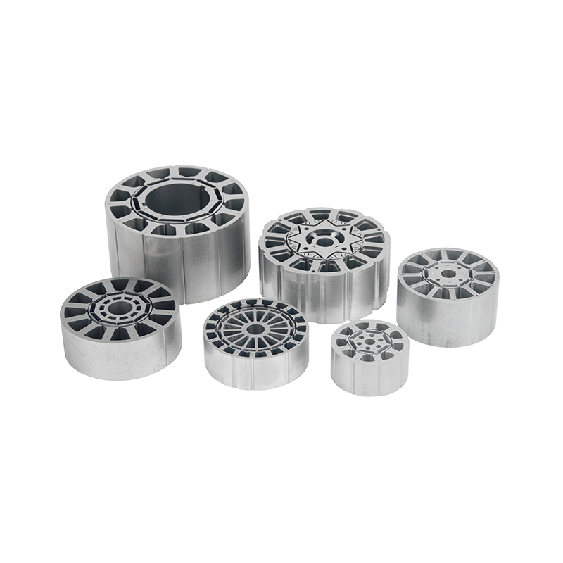
The physical structure of the stator dictates both its electrical efficiency and its manufacturing footprint. The choice between solid and segmented shapes will influence your entire supply chain. Selecting the right brushless stator core architecture requires a frank look at your assembly capabilities.
Solid stator cores feature a single, continuous piece of stamped steel. Many legacy designs rely on them. They offer distinct advantages for high-volume, cost-sensitive manufacturing.
Pros: Solid cores provide simpler manufacturing. They feature inherent structural stability. Assembly teams find them much easier to align inside a motor housing. They do not require complex secondary pressing operations.
Cons: Solid cores suffer from a lower maximum slot fill factor. Winding machines struggle to pack copper wire tightly into closed slots. Furthermore, stamping a solid stator leaves a large center cutout. This process generates a much higher scrap rate, wasting valuable silicon steel.
Segmented cores break the stator down into individual teeth. Manufacturers wind these individual pieces before assembling them into a circle. They represent the gold standard for high-performance applications.
Pros: They offer an exceptional slot fill factor. You can wind the copper wire tightly and uniformly. This density delivers higher efficiency and more torque. Segmented designs also generate nearly zero material waste during stamping. They interlock perfectly on the raw steel sheet. This geometry makes them ideal for designing a custom BLDC core tailored to exact spatial constraints.
Cons: They require advanced assembly techniques. You cannot simply drop them into a casing. Maintaining concentricity demands precise plastic overmolding or high-tension pressing rings. Any slight misalignment compromises mechanical strength and ruins the air gap.
Procurement teams often attempt to source stators and rotors from different vendors to chase minor cost savings. This strategy rarely pays off in technical applications. Sourcing a pre-matched brushless motor stator rotor core from a single facility protects system integrity.
Every manufacturing step introduces micro-inconsistencies. When you buy components from disparate vendors, these tiny dimensional deviations stack up. A rotor might run at the high end of its tolerance band. A stator might run at the low end. Putting them together creates immediate friction or magnetic imbalance. Buying matched kits eliminates this risk. The factory stamps both pieces from the exact same steel batch. They use calibrated tooling designed specifically to operate as a paired set.
The air gap between the stator and the rotor controls magnetic flux transfer. Even a fraction of a millimeter of eccentricity causes serious issues. Uneven magnetic pull creates intense side loads on the motor bearings. Matching components at the factory level ensures perfect concentricity. The supplier measures the brushless rotor core against its exact paired stator. This rigorous alignment remains non-negotiable for achieving a low-vibration profile.
Kitted components simplify life on the production floor. Your incoming quality control (IQC) team spends less time rejecting mismatched parts. This approach drastically reduces IQC bottlenecks. It also simplifies your Bill of Materials (BOM). Procurement teams deal with one supplier, one lead time, and one point of accountability. If a performance issue arises, you do not waste time mediating disputes between two different stamping houses.
Your motor core is only as good as the mold that stamps it. When evaluating a potential manufacturing partner, you must look past their marketing brochures. You need to investigate their underlying tooling infrastructure.
Always assess the supplier’s progressive stamping mold capabilities. Do they build their dies in-house, or do they outsource them? In-house mold design indicates deep engineering competence. Ask about their use of carbide dies. High stroke life in carbide dies dictates long-term consistency. A cheap steel die will degrade rapidly. It will produce burrs on the laminations after a few hundred thousand strokes. Burrs cause electrical shorts and destroy motor efficiency.
Evaluate the supplier's transition phase. Motor design requires iteration. You rarely get it right on the first try. Can the supplier provide laser-cut prototypes for validation? Laser cutting allows you to test different geometries without paying for hard tooling. Once you validate the magnetic performance, the supplier should seamlessly transition your design into high-volume progressive stamping. This flexibility saves massive amounts of upfront capital.
Demand hard evidence of quality control. Look for Coordinate Measuring Machine (CMM) data reports. The supplier should measure concentricity, slot dimensions, and stack height with micron-level accuracy. Check for ISO 9001 and IATF 16949 certifications, especially if you operate in automotive or critical industrial sectors. Finally, demand raw material traceability. Reputable suppliers source their electrical steel directly from top-tier mills. They provide material certificates proving the exact core-loss properties of the steel batch.
Engineers must carefully navigate a landscape of rigid mechanical rules when designing BLDC motors. Do not default to off-the-shelf cores for specialized applications. Let your operational realities dictate the geometry. Torque requirements, thermal limits, and assembly constraints must drive your choice between solid, segmented, or matched kits. Thinner steel and segmented designs offer incredible performance but demand robust manufacturing processes.
To move forward, stop focusing solely on unit price. Recommend starting supplier conversations with a highly detailed specification sheet. Define your target RPM, continuous torque, allowable core loss, and NVH thresholds clearly. Bring these metrics to a proven stamping partner. Discuss their tooling capabilities and material sourcing firsthand. This evidence-based approach guarantees a motor foundation built for longevity and peak efficiency.
A: Typically ranges from 0.2mm to 0.5mm. Thinner laminations (0.2mm - 0.35mm) are used for high-speed, high-efficiency applications to reduce eddy current losses, while 0.5mm is common for standard cost-sensitive motors.
A: They allow for individual coil winding, resulting in a much higher slot fill factor. This delivers higher torque in a smaller, lighter package—critical for battery-powered robotics.
A: Vibration is usually caused by uneven magnetic pull due to air gap variance, or poor rotor balancing. It is minimized by tight stamping tolerances, matched stator-rotor kits, and precise shaft assembly.
A: Depending on complexity (e.g., progressive stamping dies for segmented cores), high-volume hard tooling generally takes 4 to 8 weeks, with laser-cut prototypes available much faster for initial validation.


