

Views: 0 Author: Site Editor Publish Time: 2026-09-18 Origin: Site


High-end CNC machines and advanced automation systems rely heavily on absolute electromagnetic efficiency. Software algorithms alone cannot compensate for subpar magnetic cores when hardware limitations restrict machine precision. A reliable servo motor stator rotor core serves as the foundational element for these complex systems. It directly dictates crucial performance metrics, including torque density, thermal management, and step-accuracy in highly demanding industrial environments.
Without top-tier core construction, you risk severe overheating, magnetic saturation, and costly positioning errors during operation. This guide provides engineers, designers, and procurement teams an objective, experience-based framework. You will learn how to properly evaluate, specify, and source these critical components. We cover optimal material selection, precise lamination thicknesses, and various stacking methods. Ultimately, you will discover actionable steps for vetting suppliers and securing high-performance parts that meet your tightest operational tolerances.
Lamination quality dictates performance: Thinner silicon steel laminations (0.2mm to 0.35mm) drastically reduce eddy current losses in high-speed CNC applications.
Stacking methods require trade-offs: Evaluate interlocking, laser welding, and adhesive bonding based on their impact on mechanical rigidity vs. magnetic degradation.
Customization vs. Standardization: Custom cores are essential for highly constrained robotics form factors, whereas standard cores offer faster procurement cycles for conventional drives.
Vendor verification is critical: Reliable sourcing requires auditing a supplier's stamping die precision, material traceability, and compliance with ISO/TS standards.
Engineers often face frustrating positioning errors in complex, multi-axis machining setups. These persistent issues frequently trace back to inferior core construction. Poorly designed magnetic cores create cogging torque, which manifests as a jerky, uneven rotation at low speeds. Furthermore, uneven thermal expansion occurs when substandard materials heat up irregularly. These physical distortions compromise the mechanical accuracy of the entire machine. When the hardware fails at this micro-level, even the most advanced control software struggles to correct the resulting tool path deviations.
A high-quality servo motor core drastically improves a system's dynamic response. Rapid acceleration and deceleration rates remain vital for true precision motion control. Excellent magnetic flux distribution enables smooth, near-instantaneous speed changes without overshooting target coordinates. In robotics and high-speed CNC applications, this fluid motion translates directly into superior surface finishes, fewer rejected parts, and significantly shorter cycle times.
Hidden costs quickly emerge when industrial systems lack proper magnetic saturation and heat dissipation capabilities. High operating temperatures degrade stator winding insulation rapidly. This excess heat also travels through the motor shaft, damaging adjacent CNC motor components over time. Thermal stress causes premature bearing failure, ruins lubrication, and induces optical encoder malfunction. To avoid these expensive, cascading failures, hardware designers must prioritize the structural and electromagnetic integrity of the motor's core.
Material selection forms the absolute baseline for magnetic performance. Silicon steel, specifically cold-rolled non-oriented electrical steel, dominates the servo manufacturing industry. Standard steel grades offer acceptable baseline performance for simple, low-speed motors. However, high-grade variants feature highly optimized silicon content. More silicon actively increases the electrical resistivity of the metal matrix. This higher resistivity drastically reduces energy-draining eddy currents during operation.
We must note a crucial mechanical trade-off here. Higher silicon content makes the steel significantly more brittle. This brittleness demands highly precise, robust stamping dies to prevent microscopic edge fracturing during mass production. If micro-fractures occur, they disrupt the magnetic flux lines and lower overall efficiency.
Lamination thickness directly influences high-frequency operation efficiency. Thinner steel sheets restrict the physical space where eddy current loops can form. A standard 0.5mm thickness works perfectly well for basic industrial motors running at standard frequencies. However, high-speed CNC spindles and modern servo systems require much thinner materials. Choosing a 0.35mm or 0.2mm laminated servo core significantly cuts core losses at high switching frequencies.
The primary trade-off lies in manufacturing costs. Stamping 0.2mm sheets requires more than double the die strokes per inch of stack height compared to 0.5mm sheets. This reality increases tool wear and slows down production throughput. Engineering teams must weigh this upfront manufacturing cost against the long-term energy savings and thermal benefits.
Assembly techniques also dictate final performance. Manufacturers use various methods to bond laminations together. We evaluate these methods based on evidence and engineering realities:
Interlocking (Cleating): This method presses small dimples into the laminations, locking them together mechanically. It is highly cost-effective, automated, and fast. However, it introduces minor mechanical stress points into the steel. These points slightly degrade local magnetic permeability.
Welding (Laser or TIG): Welding provides immense structural strength along the core's exterior. It suits high-vibration environments perfectly. Unfortunately, the localized heat from the welding arc alters magnetic properties near the weld seam. This thermal shock can increase core losses by 5% to 10% if not carefully controlled.
Adhesive Bonding (Glue Bonding): This method applies a micro-layer of specialized epoxy between sheets. It maximizes magnetic efficiency and minimizes acoustic vibration. The total lack of physical stress or heat damage preserves the steel’s original properties. The main downside remains increased production time and higher piece prices due to curing cycles.
Lamination Thickness vs. Frequency Suitability Chart
Lamination Thickness | Primary Application | Optimal Frequency Range | Relative Stamping Cost |
|---|---|---|---|
0.50 mm | Standard Industrial Motors | 50 Hz - 60 Hz | Low |
0.35 mm | CNC Servos & General Robotics | 200 Hz - 400 Hz | Medium |
0.20 mm | High-Speed Spindles & Drones | 400 Hz - 1000+ Hz | High |
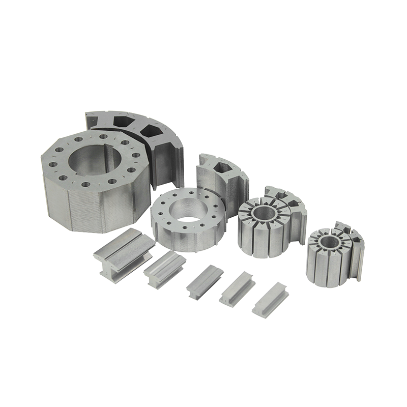
Project requirements ultimately dictate whether you choose off-the-shelf geometries or invest in bespoke tooling. Standard cores follow common NEMA or IEC frame sizes. They fit seamlessly into conventional drive housings. These pre-designed parts help engineering teams move fast and validate concepts quickly. You bypass the lengthy tooling design phase entirely. Standard cores remain the best choice for rapid prototyping, budget-constrained projects, and applications where form factor is not strictly limited.
However, standardized options frequently fall short in cutting-edge industries. Highly specialized applications demand unique geometries. A custom servo motor core becomes absolutely necessary for proprietary robotics motor core designs. For example, collaborative robot (cobot) joints require extremely high pole counts packed into very tight, flat spaces to maximize torque without adding weight. Frameless motors and hollow shaft designs also necessitate custom stamping. Designing specific inner and outer diameters allows engineers to route cables through the center or optimize the magnetic circuit perfectly for a specific load.
Tooling and lead time realities require transparent planning. Developing custom progressive dies involves notable Non-Recurring Engineering (NRE) costs. These carbide dies require extreme precision to cut thin silicon steel cleanly. Depending on geometric complexity, custom tooling can take 8 to 12 weeks to design, build, and test. You must factor this timeline into your product development cycle. For initial testing, you might use wire Electrical Discharge Machining (EDM) or laser cutting. This approach yields quick prototypes in just 2 to 4 weeks without full tooling investments. Just remember, laser cutting alters edge properties slightly, so prototype performance might differ marginally from mass-produced parts.
Finding a reliable manufacturing partner involves looking closely past slick marketing brochures. You need an objective, evidence-based framework for assessing a supplier's true technical capabilities. Evaluating vendors across specific dimensions ensures consistent quality as you scale up to mass production.
Die manufacturing capability stands as the single most critical evaluation metric. Look for suppliers who design, machine, and maintain their progressive dies entirely in-house. In-house tooling ensures rapid maintenance, quick troubleshooting, and much tighter quality control. For high-performance motor cores, stamping tolerances often need to remain within ±0.01mm. Suppliers using high-grade tungsten carbide dies achieve this incredible consistency across millions of press strokes. Relying on third-party toolmakers often leads to frustrating delays when dies need repair or adjustment.
Quality assurance and testing protocols separate average vendors from elite manufacturing partners. Ask potential suppliers about their specific validation methods. You should verify three key processes:
Epstein Frame Testing: Ensure they rigorously test incoming raw silicon steel for core loss and permeability before any stamping begins.
Coordinate Measuring Machine (CMM) Checks: Verify they use advanced CMMs for strict dimensional inspections on finished stacks to guarantee perfect concentricity.
Post-Assembly Magnetic Validation: Confirm they test the final stacked and bonded cores to ensure the chosen stacking methods haven't compromised magnetic integrity.
Supply chain resilience also demands your attention. Raw material traceability prevents sudden performance drops between production batches. Your vendor must source electrical steel directly from reputable, tier-1 steel mills. Always request official material test certificates for every shipment. This documentation ensures you actually receive the exact silicon grade specified in your technical drawings, preventing substitutions with inferior metals.
Procurement discussions often fixate heavily on the individual piece price. A much smarter strategy analyzes the broader operational return on investment (ROI). Focusing purely on upfront part costs frequently leads to expensive machine inefficiencies later. You should carefully evaluate how superior core design impacts overall machinery performance, maintenance schedules, and ongoing energy requirements.
Energy savings and machine uptime directly correlate with core quality. Minor efficiency gains from reduced core losses create a massive financial impact over a machine's lifespan. Less wasted energy means less heat generation within the motor housing. Consequently, you dramatically lower the active cooling requirements for the surrounding CNC machinery. Cooler operating temperatures preserve winding insulation and extend the life of sensitive electronic feedback devices. When motors run efficiently and coolly, factory floor downtime plummets. This increased production uptime easily offsets the minor premium paid for high-grade silicon steel and precision stamping.
Structuring a robust Request for Quote (RFQ) streamlines your shortlisting logic. Force vendors to disclose specific technical details very early in the negotiation process. Your RFQ should explicitly require suppliers to state the exact material grades they intend to use. Ask them to outline the precise stacking methods included in their quote. Demand guaranteed dimensional tolerances in writing. By comparing these highly detailed proposals side-by-side, you quickly filter out vendors who cut invisible corners to offer artificially low bids.
Supplier Capability Comparison Matrix
Evaluation Criteria | Standard Supplier Capability | Premium Supplier Capability |
|---|---|---|
Tooling Production | Outsourced to third-party toolmakers | In-house tungsten carbide progressive dies |
Raw Material Sourcing | Spot market, limited traceability | Direct from Tier-1 mills with full certificates |
Assembly Techniques | Limited to interlocking or basic welding | Offers advanced adhesive bonding options |
Tolerance Control | Maintains ±0.05mm accuracy | Consistently holds ±0.01mm or better |
Specifying a servo motor stator rotor core requires balancing multiple interconnected technical variables. You must carefully align magnetic efficiency, mechanical rigidity, and real-world production viability. Selecting the right silicon steel thickness minimizes high-frequency energy losses. Choosing the appropriate stacking method preserves crucial magnetic properties while meeting structural demands. Whether you opt for standard NEMA sizes to speed up development or commission a bespoke robotics design for a specialized form factor, rigorous vendor vetting remains non-negotiable.
Take the next step by moving from theoretical evaluation to tangible prototyping. Reach out to a verified manufacturing partner early in your design phase. Request a technical consultation to review your CAD drawings and material requirements together. A knowledgeable partner will help you navigate complex tooling timelines, refine your geometric tolerances, and ensure your next precision motion system operates flawlessly from day one.
A: The 0.35mm thickness represents the industry sweet spot for high-speed CNC applications. It perfectly balances eddy current reduction with stamping feasibility and cost. However, for ultra-high frequency applications like specialized spindles, engineers often upgrade to 0.2mm laminations to further minimize core losses.
A: Mechanical methods like welding or cleating can create microscopic electrical shorts between laminations, increasing heat generation. Adhesive bonding maintains perfect insulation between layers. This reduces heat and significantly improves torque density, which is critical for compact robotics joints.
A: Yes, but the mechanical realities require extreme precision. The stator outer diameters (OD) and rotor inner diameters (ID) must match the existing housing and shaft perfectly. You must also factor in custom winding clearance and updated potting considerations to ensure proper fitment.
A: Realistic timelines vary by method. You can expect 2 to 4 weeks for rapid laser-cut or wire-EDM prototypes. If you require full production-grade parts, developing high-precision progressive die tooling typically takes 8 to 12 weeks before first article inspection.


